

New Roundhouse: Floor Structure
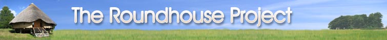
To accommodate our proposed raised timber floor, we had to erect a three foot high dry-stone column in the centre of the roundhouse. This was to be the hub of our spoke-like arrangement of joists.
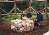
Our joists are, once again, whole Larch trees, trimmed of branches, debarked, and left to season. They are on average 12 inches wide at their bases. These wide ends sit on the lowest horizontal members of the timber frame, and nestle comfortably in between the 2 diagonal members of each wall section. The other end of the joists sit on the edge of the stone column, which will also form the base of the fireplace.
All of our joists run through the timber frame, and extend outwards past it for a further 2-3 feet. This enabled us to lay flooring along the joists on the outside of the roundhouse, to accommodate the straw bale wall, which will start at the same height as the interior floor. Each of the 12 principal joists are 8 feet apart by the time they reach the timber frame. This necessitated smaller secondary joists to reduce the distance, and give the floor more rigidity. They start 2 feet away from the central column, where they rest on their own posts. The other ends butt up against the 12 wall posts, and rest on little blocks attached to the posts. In order to support the exterior straw bale wall, small joist- extensions were added that were pinned to either side of the joists, and also to the post that they pass.
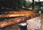
Cut into the thin ends of the first two rafters
were the two halves of a bridle joint. Cut into the other ends, were the
mortises that matched up with the post-top tenons. Once these two were lifted
and made to sit opposite each other on the post tenons, we lashed them to
the spike, and pegged the joint. The next two quartered the now halved circle
and simply rested on the others. It was at this point we dissassembled the
steel tower (which had been erected just off-center), and brought in the
movable aluminium access tower. This freed the apex so that we could peg
in two simple cross-beams.
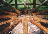
A water level was used to ensure our correct placing of joists. A clear plastic tube was attached to a stick near a chosen joist. The other end was brought up, and the tube was filled with water, until it rose to the level of our joist. The free end could now be taken anywhere in the building to check the levels. If the water in the static end is on the mark, then you know the other end will be level with it.
Home | News
| First Roundhouse | New
Roundhouse |Gallery Index
The Project | Resources
| Contact | Help
All content: © The Roundhouse Project 1997-2010